Product
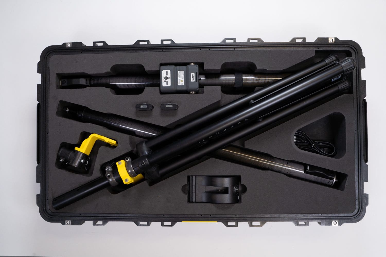
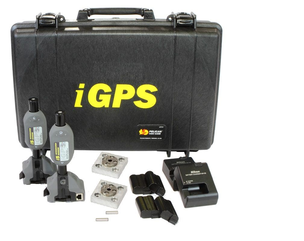
iGPS Accessories
Wired or wireless, three power options
Wired or wireless, three power options
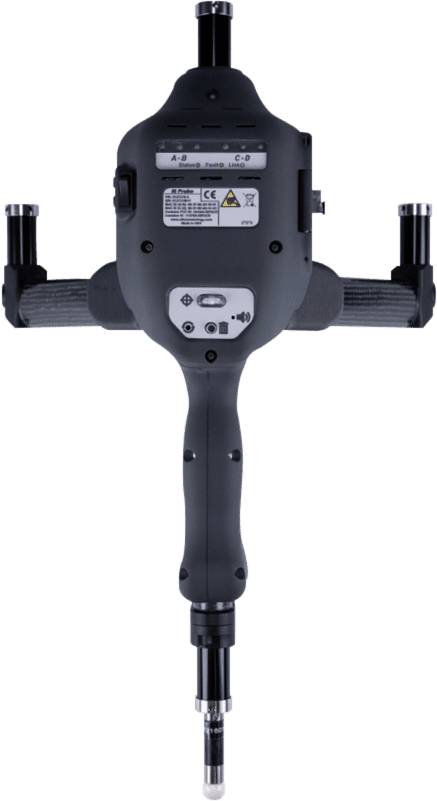
The Digital Input Module (DIM) allows up to 4 independent external events to be synchronized with iGPS measurements. The external electrical event is linked to one of four DIM channels and each event occurrence is digitized and time stamped in Surveyors time base. Each DIM channel has an LED which indicates when an event is received.
In Surveyor the digital events can be used as pure timed events with no associated action or can be configured to perform any of the following actions: Capture – Captures the current position of the assigned frame ; Undo – Undoes the last action ; Change Mode – Cycles through the measurement modes ; Change Tip – Cycles through the assigned frames tip.
Collaborative metrology
Key features of this product
In Surveyor the digital events can be used as pure timed events with no associated action or can be configured to perform any of the following actions:

Capture
Captures the current position of the assigned frame

Undo
Undoes the last action
Change Mode
Cycles through the measurement modes
Change Tip
Cycles through the assigned frames tips

How that work
The Science Behind iGPS
iGPS (Indoor Global Positioning System) operates by creating a network of laser transmitters that emit modulated, rotating laser beams across a defined workspace. Wireless sensors mounted on tools, parts, or probes detect these laser sweeps and record the precise time and angle at which each beam passes. By analyzing the timing and angular data from multiple transmitters, the system triangulates the exact 3D position and orientation (6DOF) of each sensor in real time. This distributed, scalable architecture allows iGPS to deliver sub-millimeter accuracy across large volumes, enabling dynamic tracking and precision measurement directly on the factory floor.
1
Transmitter Placement & Initialization
Calibration begins by strategically placing iGPS laser transmitters around the measurement volume. Their positions must be stable and provide overlapping coverage of the workspace.
2
Reference Sensor Setup
A reference sensor or calibrated object (such as a known artifact or fixture) is used to establish a baseline. This helps define the coordinate system and ensures consistency across the network
3
System Self-Calibration
iGPS systems often support self-calibration with monuments, where the system uses known distances and angles between transmitters and sensors to automatically refine their positions and orientations. This step ensures that all transmitters are correctly aligned within a unified coordinate frame.
4
Sensor Validation
Sensors (e.g., on an iProbe or tool) are verified against known reference points to ensure their readings match expected values. Any deviations are corrected through software compensation or re-alignment.
5
Environmental Compensation
The system may apply corrections for temperature, humidity, or air turbulence, which can affect laser propagation and measurement accuracy.
6
Verification & Repeatability Testing
After calibration, the system is tested by measuring known points or performing repeatability checks to confirm accuracy and stability.
iGPS Calibration Process (General Overview)
Technical Specifications
Explore the complete technical details of the iGPS system to ensure optimal integration and performance. Review the specifications to confirm compatibility and achieve the highest precision in your measurement workflows.
Hardware Specifications (sensor dimensions, weight, power requirements, and connectivity options)
Software Requirements (supported operating systems, compatibility details, and recommended configurations)
Performance Metrics (accuracy, range, environmental tolerances, and calibration standards)
Compliance & Certifications (industry standards and safety certifications for reliable operation)
Documents
to download
Get the official documentation for iGPS to support your installation, configuration, and operation needs. This download includes: User Manuals (detailed instructions for setup and usage), Technical Specifications (comprehensive hardware and software details), Quick-Start Guides (step-by-step instructions for fast deployment) and Troubleshooting Resources (solutions for common issues and FAQs).
Unlock documents
Fill this form to download the document.
Collaborative metrology
Why choose our technology
1
Precision and accuracy
iGPS provides highly accurate positioning and tracking, which is essential for applications requiring fine measurements.
2
Real-time data
iGPS delivers real-time positioning data, enabling quick decision-making and immediate feedback during operations.
3
Simultaneous and multi-point measurement
iGPS can measure the moving positions of several points or objects at the same time, which is particularly useful in complex setups or large factories with many working cells.
4
Integration and collaborative capabilities
iGPS can easily integrate with existing technologies and workflows, ensuring not only compatibility but collaboration with other systems.
5
Scalability
iGPS can be scalable to fit a range of applications from small setup to large industrial environments, making it versatile.
Collaborative metrology